
Understanding circuit board components is essential for designing, repairing, and optimizing electronic devices. Identifying components helps in troubleshooting, ensuring compatibility, and maintaining functionality. This guide provides insights into recognizing key elements, from resistors and capacitors to advanced ICs, and offers practical tips for beginners and professionals alike.
What Are Circuit Board Components?
Circuit board components are the fundamental building blocks of electronic circuits, mounted on a printed circuit board (PCB) to perform specific functions. These components include passive elements like resistors, capacitors, and inductors, which control voltage, current, and frequency. Active components, such as transistors and integrated circuits (ICs), amplify or process signals. Transformers, relays, and diodes are also common, serving roles like voltage transformation, signal switching, and polarity control. Each component is designed to fulfill a unique purpose, ensuring the overall functionality of the electronic system. Proper identification of these components is crucial for troubleshooting, repair, and design optimization. Understanding their roles and characteristics is essential for anyone working with electronics, from beginners to professionals.
Why Is Identifying Components Important?
Identifying circuit board components is crucial for troubleshooting, repairing, and designing electronic systems. Proper recognition ensures accurate diagnostics, preventing costly errors and downtime. It enables effective quality control during manufacturing, verifying that all parts meet specifications. Component identification also aids in inventory management, ensuring the right parts are stocked and used. For engineers and technicians, understanding components facilitates system optimization and upgrades. In educational settings, it helps learners grasp electronic fundamentals. Accurate identification is vital for safety, as incorrect parts can lead to malfunctions or hazards. Overall, component identification is essential for maintaining reliability, efficiency, and performance in electronic devices and systems. It serves as the foundation for all PCB-related tasks, ensuring every component functions as intended within the broader circuit.
Challenges in Identifying PCB Components
Identifying PCB components can be challenging due to their small size, complex designs, and lack of clear labeling. Miniaturized parts, such as surface-mount devices (SMDs), are difficult to distinguish visually. The absence of standardized markings across manufacturers complicates recognition. Environmental factors like dust or solder residue can obscure identifiers. Additionally, components may be hidden under protective coatings or embedded within multi-layer boards. Beginners often struggle with limited familiarity with component shapes and symbols. Advanced components, such as ICs, require specialized knowledge or tools for accurate identification. These challenges highlight the need for systematic approaches, such as visual inspection, reference designators, and automated tools, to ensure accurate and efficient component identification. Overcoming these obstacles is crucial for successful PCB repair, design, and quality control.
Key Techniques for Identifying Circuit Board Components
Mastering component identification involves visual inspection, reference identifiers, and automated tools. Visual inspection helps recognize shapes and labels. Reference designators guide understanding of component types. Automated tools enhance accuracy and efficiency in recognizing complex parts. These techniques ensure precise identification for effective PCB analysis and repair.
Visual Inspection and Its Role in Component Identification
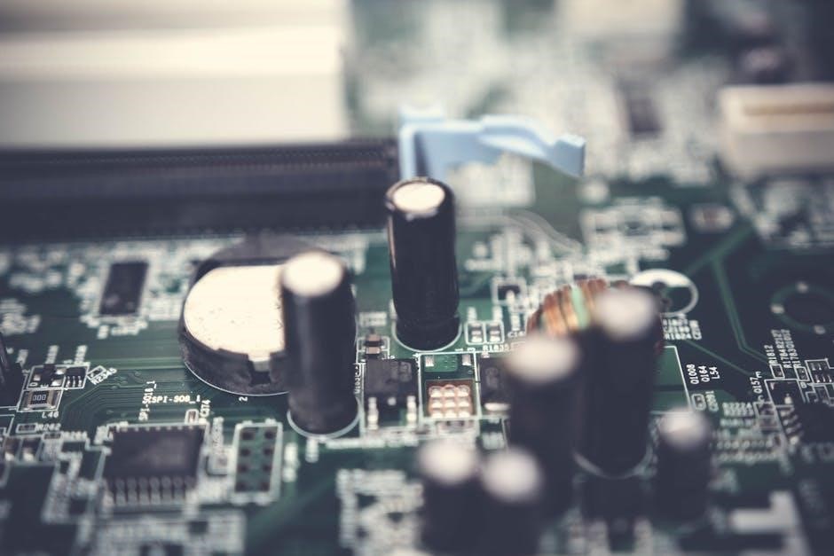
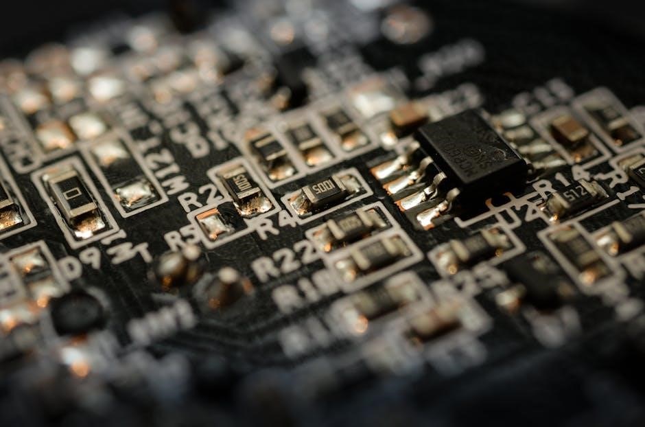
Visual inspection is a foundational technique in identifying circuit board components. By closely examining the PCB, one can recognize components based on their shape, size, color, and labeling. Resistors, for instance, are often rectangular with colored bands, while capacitors may appear cylindrical or rectangular with capacitance values printed. Diodes and transistors typically have distinct packaging, and ICs are usually identifiable by their multiple pins and part numbers. Using magnification tools like microscopes or loupe lamps can enhance clarity. This method is particularly useful for beginners, as it relies on observable features rather than advanced tools. However, it requires familiarity with component shapes and markings, making it more challenging for complex or miniature parts. Visual inspection is often the first step in component identification, providing a baseline for further analysis.
Using Reference Identifiers and Designators
Reference identifiers and designators are crucial aids in circuit board component identification. Each component is typically labeled with a combination of letters and numbers, where the letter denotes the component type. For example, ‘R’ stands for resistors, ‘C’ for capacitors, and ‘Q’ for transistors. Numbers following these letters often indicate the specific part or location on the board. These designators are standardized, making it easier to cross-reference components with schematics or datasheets. By using these identifiers, technicians and engineers can quickly locate and verify components, ensuring efficient troubleshooting and assembly. This systematic approach minimizes confusion, especially in densely populated PCBs, and is indispensable for both manual and automated identification processes. Mastery of reference identifiers is a key skill for anyone working with electronic circuits.
Automated Tools for Component Identification
Automated tools have revolutionized the process of circuit board component identification, offering unparalleled accuracy and efficiency. Tools like the DXF Overlay app enable users to search and identify components quickly, while automated traceability solutions provide real-time data on parts. These systems use advanced algorithms to recognize patterns, labels, and even miniature components, reducing human error. AI-powered solutions are increasingly being integrated to enhance recognition capabilities, particularly for complex or densely populated boards. Such tools are invaluable in quality control and high-volume manufacturing, ensuring components are correctly placed and functional. By streamlining identification, automated tools save time and improve productivity, making them essential for modern electronics manufacturing and repair workflows.

Common Components Found on Circuit Boards
Resistors, capacitors, inductors, diodes, transistors, and integrated circuits (ICs) are essential components on circuit boards, each serving unique roles to enable electronic functions and ensure proper circuit operation.
Resistors: Function, Types, and Identification
Resistors are fundamental components that limit current flow in a circuit by providing opposition to voltage. They are crucial for voltage division, signal attenuation, and heat dissipation. Fixed resistors maintain a constant resistance, while variable resistors, like potentiometers, allow adjustable resistance values. Resistors are identified by their color-coded bands or surface-mount technology (SMT) labels. The reference designator “R” often precedes resistor labels on circuit boards. Understanding resistor types, such as carbon film, metal film, or power resistors, is vital for circuit functionality. Proper identification ensures correct voltage and current handling, preventing circuit damage. Resistors are among the most common and essential components, making their recognition a cornerstone of circuit board analysis.
Capacitors: Types, Symbols, and Identification Tips
Capacitors store electrical energy in an electric field, filtering, smoothing, and regulating voltage in circuits. They are categorized into types like ceramic, electrolytic, and film capacitors, each suited for specific applications. Capacitors are represented by symbols such as two parallel lines or a curved line with a straight line. The reference designator “C” often labels capacitors on PCBs. Identification involves recognizing their shape, size, and markings. Electrolytic capacitors are typically cylindrical with polarity indicators, while ceramic capacitors are smaller and disk-shaped. Understanding capacitor types and symbols is crucial for circuit functionality. Proper identification ensures correct voltage handling and prevents circuit malfunctions. Capacitors play a vital role in filtering and energy storage, making their recognition essential in circuit board analysis.

Inductors: How to Recognize and Understand Their Role
Inductors are essential components in electronic circuits, storing energy in a magnetic field when current flows. They are typically recognized by their coiled wire structure. Inductors filter, tune, and regulate frequency in circuits. The reference designator “L” identifies them on PCBs. They come in various types, including air core, iron core, and ferrite core inductors. Identifying inductors involves examining their shape and coil pattern. Understanding their role is crucial for circuit functionality, as they oppose changes in current. Proper identification ensures optimal performance in filtering and tuning applications. Inductors are vital in circuits requiring specific frequency responses, making them indispensable in modern electronics. Their role in managing magnetic fields ensures smooth operation in a wide range of applications.
Diodes: Identification and Common Types
Diodes are fundamental components in electronic circuits, acting as one-way switches for current flow. They are easily identified by their distinctive arrow symbol on schematics and typically have a rectangular or cylindrical shape with two terminals. The reference designator “D” marks them on PCBs. Common types include rectifier diodes for AC-to-DC conversion, Zener diodes for voltage regulation, Schottky diodes for high-speed switching, and LED diodes for light emission. Identifying diodes involves checking their markings and understanding their role in blocking reverse current. Proper identification ensures correct voltage handling and circuit protection. Diodes are crucial in power supplies, signal demodulation, and logic circuits. Their versatility makes them indispensable in modern electronics.
Transistors: Structure, Function, and Identification
Transistors are essential semiconductor devices that amplify or switch electronic signals. They consist of three layers of semiconductor material, forming two p-n junctions, and have three terminals: base, collector, and emitter. On PCBs, transistors are typically marked with the reference designator “Q.” Their function varies based on type, with bipolar junction transistors (BJTs) and field-effect transistors (FETs) being common. BJTs amplify current, while FETs control voltage. Identifying transistors involves checking their package type, such as TO-92 or SOT-23, and their part number. Common types include NPN and PNP transistors for switching and amplification. Proper identification ensures correct functionality in circuits, from power management to signal amplification. Transistors are vital in driving loads, switching circuits, and amplifying weak signals in electronic systems.
Integrated Circuits (ICs): How to Identify and Understand Their Purpose
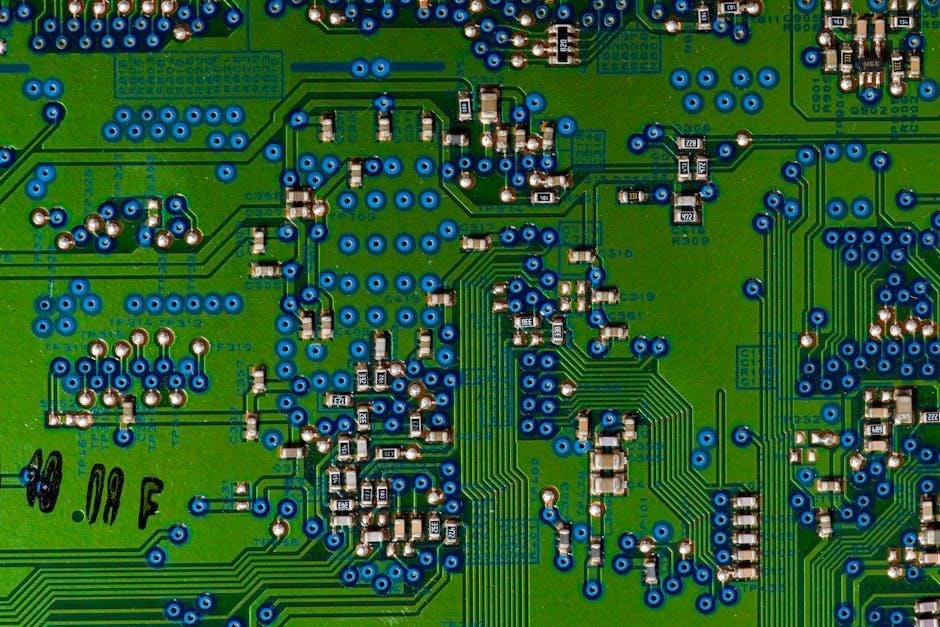
Integrated Circuits (ICs) are complex semiconductor devices containing multiple electronic components on a single chip. They are essential for modern electronics, performing functions like processing, memory storage, and signal control. On PCBs, ICs are typically identified by their unique part numbers and reference designators, often starting with “U” or “IC.” Their purpose ranges from microprocessing to voltage regulation. Identifying ICs involves examining their packaging, such as DIP, SOIC, or BGA, and cross-referencing with datasheets. Common types include microcontrollers, memory chips, and operational amplifiers. Proper identification ensures compatibility and functionality in circuits, enabling efficient design and troubleshooting. ICs play a crucial role in miniaturizing electronics and enhancing performance across various applications.
Advanced Components and Their Identification
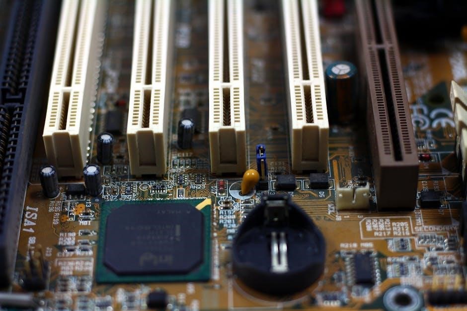
Advanced components like oscillators, transformers, and relays are easily identifiable by their unique shapes and markings, serving critical roles in signal processing, power management, and circuit control.
Oscillators: Easy-to-Identify Features and Functions
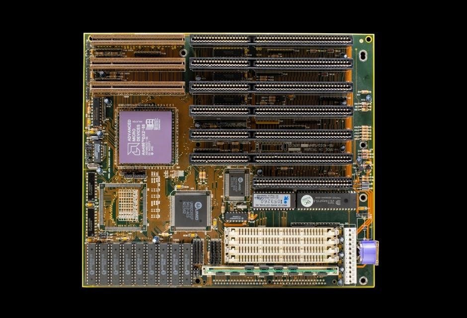
Oscillators are essential components that generate stable frequencies for timing and signal generation in electronic circuits. They are often cylindrical or rectangular in shape, with distinct markings like “X” or “Y.” These components are crucial in applications such as microcontrollers, communication devices, and clock circuits. Key features include their ability to produce precise frequencies, making them indispensable for synchronization and timing control. Oscillators are typically easy to identify due to their unique packaging and labeling, which often includes their frequency rating. Their functionality revolves around converting DC power into AC signals at a specific frequency, ensuring reliable operation in various electronic systems. Understanding oscillators is vital for diagnosing timing-related issues and optimizing circuit performance.
Transformers: How to Spot and Understand Their Role
Transformers are vital circuit board components designed to transfer electrical energy between circuits through electromagnetic induction. They are easily identifiable by their distinctive shape, typically a circular or rectangular core with windings of copper wire. Transformers are labeled with a “T” designation and often have their specifications, such as voltage and current ratings, printed on them. Their primary function is to step up or step down AC voltages, ensuring compatibility between different parts of a system. This makes them essential in power supplies, audio equipment, and telecommunication devices. Identifying transformers is straightforward due to their unique appearance and labeling, allowing for efficient troubleshooting and component replacement. Their role in voltage regulation is critical for maintaining the stability and performance of electronic circuits.
Relays: Function, Types, and Identification Methods
Relays are electro-mechanical or solid-state devices that act as electrically controlled switches, enabling the regulation of high-current circuits using low-current signals. They are crucial for isolating circuits, enhancing safety, and improving system efficiency. Relays are typically labeled with a “K” designation and can be identified by their rectangular or cylindrical shape, often featuring a coil and movable contacts. Common types include electromechanical relays, solid-state relays, and reed relays, each suited for different applications. Identifying relays involves checking their packaging, terminal layout, and labels. They play a key role in power management, circuit protection, and signal control, making them indispensable in automotive, industrial, and consumer electronics. Understanding their function and types aids in proper identification and effective use in various systems.
Manufacturing Considerations and Component Identification
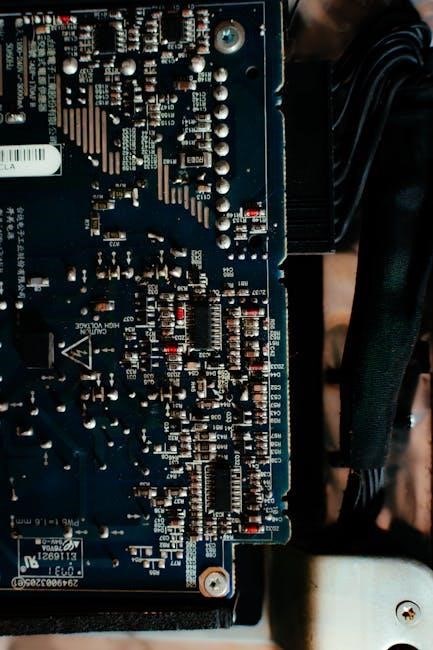
Manufacturing processes significantly influence component identification on circuit boards. Techniques like through-hole and surface-mount assembly affect component placement and labeling. Quality control measures ensure accuracy and reliability in PCB assembly, while traceability solutions enhance production efficiency and defect detection. Proper identification methods are vital for maintaining consistency and performance in electronic devices. Understanding these considerations helps optimize manufacturing workflows and ensures component functionality across various applications, from consumer electronics to industrial systems.
Through-Hole vs. Surface-Mount Components: Key Differences
Through-hole and surface-mount components are two primary types used in PCB assembly, each with distinct characteristics. Through-hole components have leads that are inserted into drilled holes in the circuit board and soldered on the underside. This method provides strong mechanical bonds, making it suitable for high-reliability applications. In contrast, surface-mount components are mounted directly onto the board’s surface, with leads soldered to pads. SMT components are smaller, enabling compact designs and higher-density circuits. The choice between through-hole and surface-mount depends on design requirements, space constraints, and manufacturing processes. Through-hole components are often used for prototyping and applications requiring durability, while surface-mount technology (SMT) is preferred for modern, miniaturized electronics. Understanding these differences is crucial for effective PCB design and assembly.
Quality Control in PCB Component Identification
Quality control is essential for ensuring accuracy and reliability in PCB component identification. It involves verifying that all components are correctly identified, properly placed, and meet specified standards. Manual inspection by technicians, using datasheets and visual checks, is a traditional method, though time-consuming. Automated tools, such as optical scanners and AI-driven systems, enhance efficiency and reduce human error. Advanced software solutions can analyze component markings, track traceability, and validate soldering quality. Implementing robust quality control measures minimizes assembly errors, ensures device functionality, and prevents costly rework. By integrating both manual and automated techniques, manufacturers can maintain high standards and deliver reliable PCBs for various applications.
Future Trends in Circuit Board Component Identification
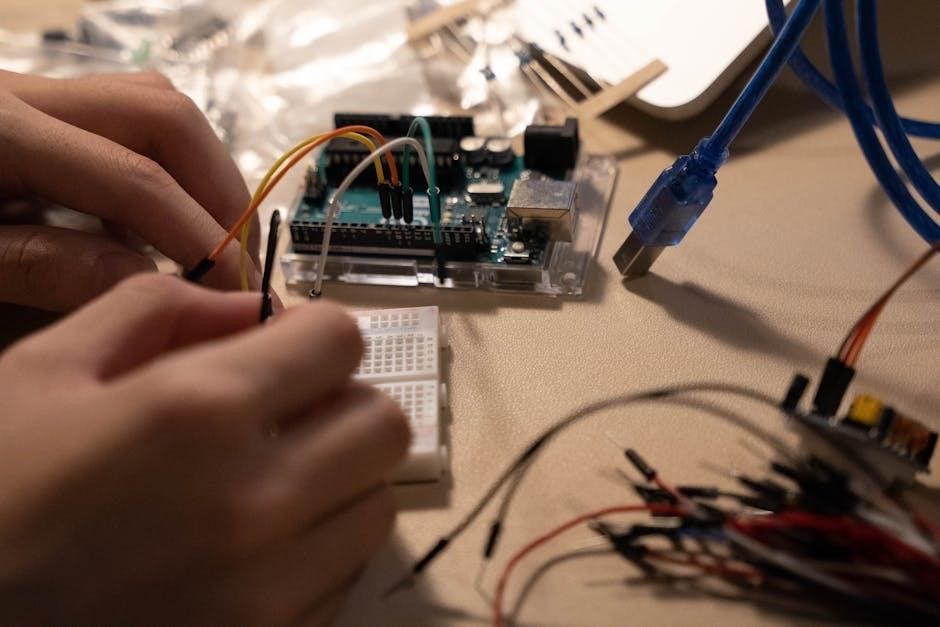
Advancements in AI and machine learning are revolutionizing PCB component identification, enabling faster and more accurate recognition. Automated tools and real-time data analysis will drive future innovations in this field.
Artificial Intelligence and Machine Learning in Component Recognition
Artificial Intelligence (AI) and Machine Learning (ML) are transforming the way PCB components are identified. These technologies enable automated systems to recognize components with high accuracy, reducing human error. AI-powered tools, such as automated optical inspection systems, can quickly scan and identify components, even in complex layouts. Machine learning algorithms analyze patterns and markings on components, improving recognition over time. Advanced systems can also predict component functionality and detect defects. Additionally, AI-driven solutions like the DXF Overlay app simplify quality control by enabling users to search and identify components efficiently. These innovations are particularly valuable in high-volume manufacturing, where speed and precision are critical. By integrating AI and ML, the future of PCB component identification promises to be faster, more accurate, and scalable for evolving electronic needs.

